
 数据结构
数据结构 网络
网络 RDBMS
RDBMS 操作系统
操作系统 Java
Java iOS
iOS HTML
HTML CSS
CSS Android
 Python
 C语言编程
C语言编程 C++
C++ C#
C# MongoDB
 MySQL
MySQL Javascript
 PHP
PHP基于Arduino的RTOS入门
RTOS代表**实时操作系统**。它用于并发运行多个任务,按需调度任务,并使它们能够共享资源。虽然本文不详细介绍RTOS的细节,但我们将逐步讲解一个示例,让您对RTOS有一个大致了解。目前,您只需注意,RTOS 将帮助您在 Arduino 中执行多任务处理,就像您计算机上的操作系统帮助您同时运行多个任务(例如撰写邮件、收听音乐等)一样。
由于我们关注的是微控制器,我们将使用**FreeRTOS**,这是一个用于嵌入式设备的RTOS。基本上,它设计得足够小,可以支持微控制器。您可以在此处阅读更多关于 FreeRTOS 的信息:https://en.wikipedia.org/wiki/FreeRTOS
现在,要在Arduino上开始使用FreeRTOS,我们首先需要一个外部库。转到**工具 -> 管理库**,然后搜索**FreeRTOS**。
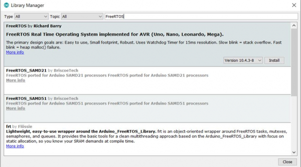
您将看到Richard Barry的库。如前所述,它适用于**Uno**、**Nano**、**Leonardo**和**Mega**开发板。我们使用的是Uno开发板,因此我们将安装此库。
库安装完成后,您将能够在**文件 -> 示例**中看到与该库相关的所有示例代码。

建议您仔细阅读所有示例以进一步了解FreeRTOS。我们将逐步讲解其中一个示例:**Blink_AnalogRead**。
如您所见,我们首先包含库
#include <Arduino_FreeRTOS.h>
之后,我们声明两个任务:Blink任务和AnalogRead任务。
void TaskBlink( void *pvParameters );
void TaskAnalogRead( void *pvParameters );
请注意,它接收**pvParameters**指针作为输入。我们稍后会再讨论这一点。
接下来是重要的设置部分。
示例
// the setup function runs once when you press reset or power the board
void setup() {
   // initialize serial communication at 9600 bits per second:
   Serial.begin(9600);
   while (!Serial) {
      ; // wait for serial port to connect. Needed for native USB, on LEONARDO, MICRO, YUN, and other 32u4 based boards.
   }
   // Now set up two tasks to run independently.
   xTaskCreate(
      TaskBlink
      ,   "Blink"    // A name just for humans
      ,   128   // This stack size can be checked & adjusted by reading the Stack Highwater
      ,   NULL
      ,   2   // Priority, with 3 (configMAX_PRIORITIES - 1) being the highest, and 0 being the lowest.
      ,   NULL );
   xTaskCreate(
      TaskAnalogRead
      ,   "AnalogRead"
      ,   128   // Stack size
      ,   NULL
      ,   1   // Priority
      ,   NULL
   );
   // Now the task scheduler, which takes over control of scheduling individual tasks, is automatically started.
}
请注意此部分中的所有注释。
我们首先初始化串口,然后等待其初始化。
然后,我们使用xTaskCreate创建任务。xTaskCreate的语法如下:
语法
BaseType_t xTaskCreate(TaskFunction_t pvTaskCode,const char * const pcName,configSTACK_DEPTH_TYPE usStackDepth,void *pvParameters, UBaseType_t uxPriority,TaskHandle_t *pxCreatedTask);
- **pvTaskCode**是执行任务的函数名称(**TaskBlink**和**TaskAnalogRead**)。
- **pcName**是任务的名称(如注释中所述,仅供人类参考)。
- **usStackDepth**是分配给任务堆栈的字数。请参考您的开发板的数据手册以确定一个字等于多少字节。
- **pvParameters**是要传递给已创建任务的参数。还记得在声明任务时使用的**pvParameters**参数吗?它们就是从这里来的。例如,您想向任务传递数字1,可以通过将(void *) 1传递给**xTaskCreate**的**pvParameters**参数来实现。
- **uxPriority**定义任务的优先级。数字越大,优先级越高。
- **pxCreatedTask**是任务句柄。这是可选的,您可以传入NULL。它的目的是在代码的其他部分引用任务。
创建任务后,如注释中所述,任务调度程序会自动启动。接下来,我们的循环为空,因为我们在任务中执行代码。
最后,定义了两个任务的函数。
示例
void TaskBlink(void *pvParameters)   // This is a task.
{
   (void) pvParameters;

/*
   Blink
   Turns on an LED on for one second, then off for one second, repeatedly.
   Most Arduinos have an on-board LED you can control. On the UNO, LEONARDO, MEGA, and ZERO, it is attached to digital pin 13, on MKR1000 on pin 6. LED_BUILTIN takes care of use the correct LED pin whatever is the board used.
   The MICRO does not have a LED_BUILTIN available. For the MICRO board please substitute the LED_BUILTIN definition with either LED_BUILTIN_RX or LED_BUILTIN_TX. e.g. pinMode(LED_BUILTIN_RX, OUTPUT); etc.
   If you want to know what pin the on-board LED is connected to on your Arduino model, check the Technical Specs of your board at https://www.arduino.cc/en/Main/Products

   This example code is in the public domain.
   modified 8 May 2014
   by Scott Fitzgerald
   modified 2 Sep 2016
   by Arturo Guadalupi
*/

   // initialize digital LED_BUILTIN on pin 13 as an output.
   pinMode(LED_BUILTIN, OUTPUT);

   for (;;) // A Task shall never return or exit.
   {
      digitalWrite(LED_BUILTIN, HIGH);    // turn the LED on (HIGH is the voltage level)
      vTaskDelay( 1000 / portTICK_PERIOD_MS ); // wait for one second
      digitalWrite(LED_BUILTIN, LOW);      // turn the LED off by making the voltage LOW
      vTaskDelay( 1000 / portTICK_PERIOD_MS ); // wait for one second
   }
}

void TaskAnalogRead(void *pvParameters)   // This is a task.
{
   (void) pvParameters;

/*
   AnalogReadSerial
   Reads an analog input on pin 0, prints the result to the serial monitor.
   Graphical representation is available using serial plotter (Tools > Serial Plotter menu)
   Attach the center pin of a potentiometer to pin A0, and the outside pins to +5V and ground.
   This example code is in the public domain.
*/

   for (;;)
   {
      // read the input on analog pin 0:
      int sensorValue = analogRead(A0);
      // print out the value you read:
      Serial.println(sensorValue);
      vTaskDelay(1);   // one tick delay (15ms) in between reads for stability
   }
任务中的注释很好地解释了代码。请注意,在任务中,我们使用任务中的**vTaskDelay()**代替**delay()**。**vTaskDelay(1)** 引入 1 个 tick 的延迟。1 个 tick 可能对应 1ms,也可能不对应。如**AnalogRead**任务的注释中所述,1 个 tick 对应 15ms。这取决于开发板的时钟频率。为了获得以毫秒为单位的延迟时间,我们可以将毫秒时间除以**portTICK_PERIOD_MS**常量。如**TaskBlink**中所做的那样,1 秒的延迟通过以下命令实现:**vTaskDelay( 1000 / portTICK_PERIOD_MS );**
您可以在此处阅读更多关于 freeRTOS 的信息:https://www.freertos.org/

968 次浏览
